Overview
Biodegradable and recycled filaments have a lower environmental impact, but they are often weaker and less predictable than virgin plastic. PLA can lose more than 20% of its tensile strength after multiple recycling cycles. As a result, they are rarely used for load-bearing parts.
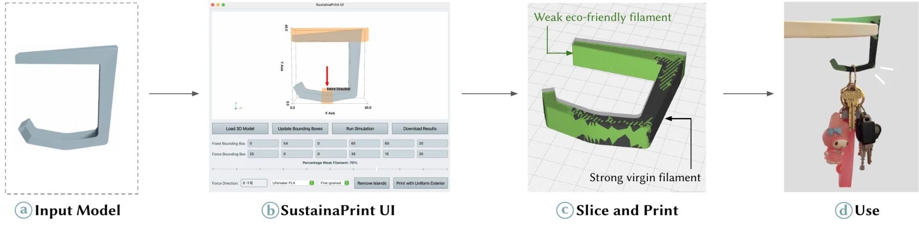
SustainaPrint combines both filaments in a single print. A finite element simulation finds the regions of a model most likely to fail. Those get a strong virgin filament, and everything else gets the eco-friendly one. The output is two STL files that a dual-extrusion printer prints as one part.
A system that combines sustainable and standard filament in one print, reinforcing structurally critical areas.
A user interface for specifying materials and use conditions, and for exploring the strength vs. sustainability trade-off.
An evaluation on real objects: prints with 80% biodegradable filament are significantly stronger than prints made entirely from eco-friendly filament.
All computation on this page runs in the browser. The app and the code boxes run the Python implementation with SfePy in Pyodide. The interactive figures use a C++ port compiled to WebAssembly, so they can update while you drag. Meshing uses fTetWild compiled to WebAssembly.
Walkthrough
An interactive version of Figure 2. Pick a model and step through the five stages. The examples use cached fTetWild meshes made with the release; simulation and segmentation run in your browser. Mesh live meshes the STL in the browser instead (about 20–35 s for these models). Drag to rotate; scroll or pinch to zoom.
The workflow
- Upload the model you want to print.
- Specify use: in the UI, mark the fixed region and where and in which direction force is applied.
- Simulate: a simulation estimates internal stress and highlights areas most likely to fail in weak material (typically 1–2 minutes with SfePy and fTetWild).
- Choose the mix: pick a percentage of eco-friendly material with a slider. SustainaPrint segments the model and generates two STLs, one for strong filament and one for eco-friendly filament.
- Print: slice both STLs together and print with a dual-material workflow.
Method · Steps 1–2
Simulating stress to find weak regions
SustainaPrint runs a finite element analysis (FEA) with the open-source library SfePy. The model is first meshed into tetrahedra. The user supplies boundary conditions: a fixed support zone, a force application region, and an approximate force direction and magnitude. The simulation is linear elastic and uses the material properties of the weaker filament. It assigns every tetrahedron a von Mises stress, and that stress map drives segmentation.
The code boxes below run Python in the browser (Pyodide with SfePy, NumPy and SciPy). Each box has a short script that applies one step to a wall hook, followed by the code from the release (sustainaprint.py) that it calls. The first run downloads about 35 MB.
You can edit any box and press Run or Shift+Enter. Running a box also runs the boxes above it, and the boxes share variables.
Start from an STL
A wall hook (Wall Hook by PRSPR on Printables, CC0), loaded from its STL file. It is screwed to the wall at its back face and loaded inside its curve.
1 · Fill the shape with tetrahedra
FEA requires a volume mesh. As in the paper, the STL is tetrahedralized with fTetWild using its default settings: a target edge length of 1/20 and an envelope of 1/1000 of the bounding-box diagonal. The release calls fTetWild through its Python bindings, wildmeshing; in the browser a stand-in with the same interface runs fTetWild compiled to WebAssembly. This box starts from the mesh the release made of this file; Mesh live meshes the STL in the browser instead.
2 · Simulate with SfePy
The simulation is a single function. It turns the two UI boxes into SfePy facet regions: a facet (a triangle of a tetrahedron) is in a box when its three corners are inside, so facets inside the part count too, once for each tetrahedron that owns them. Nodes of the fixed region are clamped. The weak form balances the internal elastic forces (dw_lin_elastic, with the stiffness of the weak filament) against a constant traction on the pushed facets (dw_surface_ltr). The problem is linear, so one Newton step with a direct sparse solver solves it. The stress is then averaged per tetrahedron and reduced to one von Mises value per element.
The computed displacement, exaggerated to show how the hook bends.
Method · Step 3
Segmenting the model into strong and weak regions
Two modes convert the stress field into a material assignment. The UI offers both, trading structural precision against ease of printing.
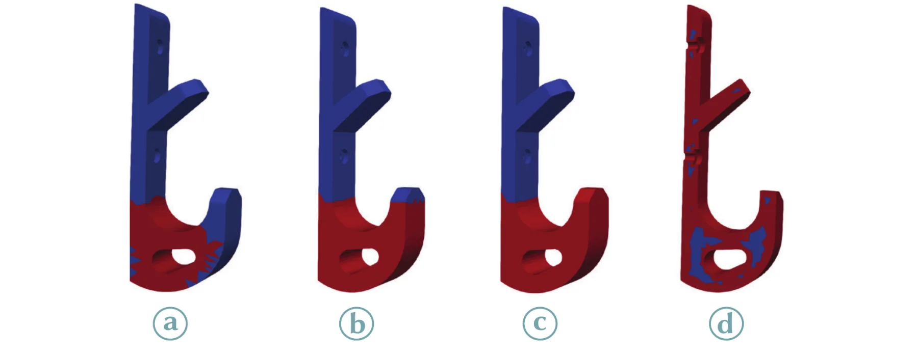
Per-tetrahedron segmentation
Each element is labeled by its stress percentile. By default the top 10% of elements are strong. This uses the most eco-friendly material but can leave fragmented regions that are harder to print.
Layer-aligned segmentation
To simplify printing, the strong region is bounded by one plane along the print (Z) axis: either everything above the lowest high-stress element becomes strong, or everything below the highest one, whichever needs less strong material. The planar boundary avoids switching materials within a layer.
Comparing the two modes
Figure 3a and 3b for any of the example models. The views update as you drag.
Method · Step 3, continued
Heuristics for printability and appearance
Island removal
Small isolated pockets of strong material are reassigned to weak material if their volume falls below a user threshold. This reduces the number of material switches.
Uniform outer shell
The outermost n layers of tetrahedra get one filament, for a consistent look. A virgin shell can hide colour or texture differences of eco-friendly infill. The finer the mesh, the thinner this layer can be. It can also be set up directly in the slicer.
4 · Two STL files
The output is one STL per filament: the outer boundary of the strong elements and of the weak ones. Faces shared by a strong and a weak tetrahedron appear in both files and become the material interface. Slice both together for a dual-extrusion printer.
Method · Step 4
Interlocking interface structures
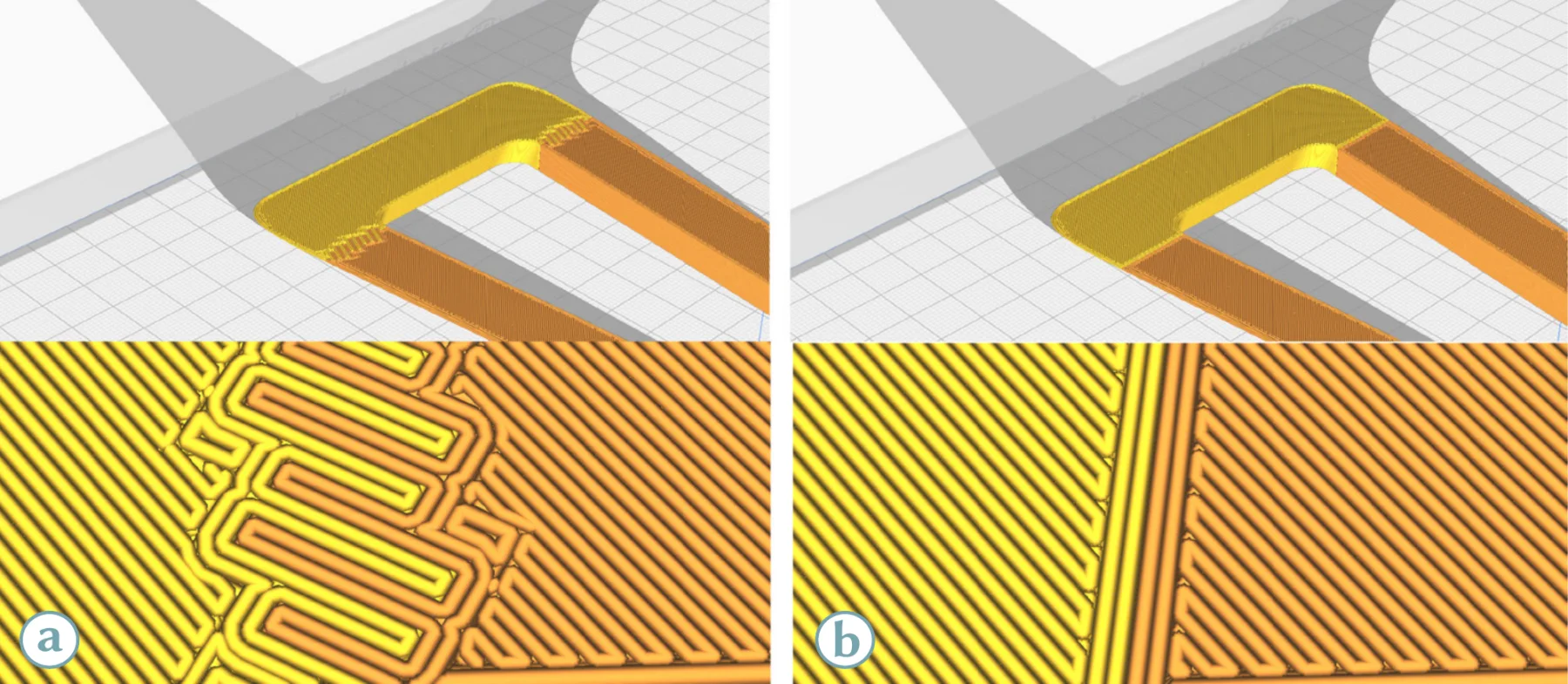
Interfaces between different filaments are common failure points, especially when the materials print at different temperatures. Following Multi-ttach, SustainaPrint relies on Ultimaker Cura's interlocking structures feature. It generates zig-zag, comb-like patterns at the material interface, which increase contact area and resist separation. Because this happens at slicing time, users enable it after segmentation without changing the geometry.
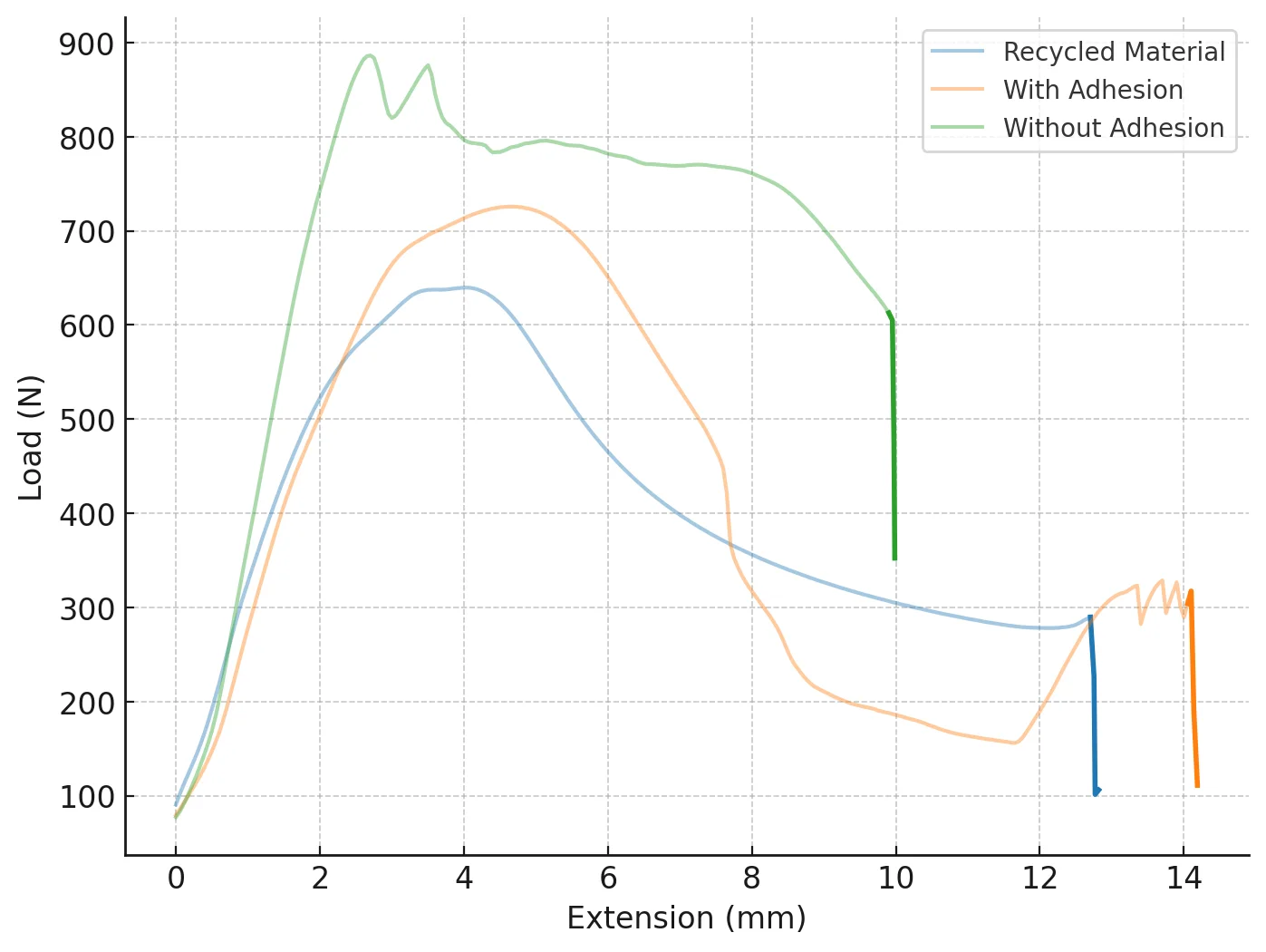
| Condition | Compression at break (mm) | Change |
|---|---|---|
| Eco-friendly (baseline) | 12.79 | 0% |
| Without interlocking | 10.05 | −21.4% |
| With interlocking (ours) | 14.21 | +11.1% |
The segmented model outperformed the all-eco-friendly print only with interlocking enabled.
The user interface
The interface guides makers through dual-material setup without exposing FEA details:
- Input model and materials. Load a model and pick the two filaments from presets, or enter their properties.
- Specify usage. Place the support and force boxes on the model and enter an estimated force direction, shown as an arrow.
- Choose a strategy. Fine-grained or layer-aligned segmentation, with island removal and shell options.
- Review and iterate. If too much of the model is virgin material, move the "percentage weak filament" slider or switch modes.
- Export. Download one STL per material and print on a dual-extruder printer.
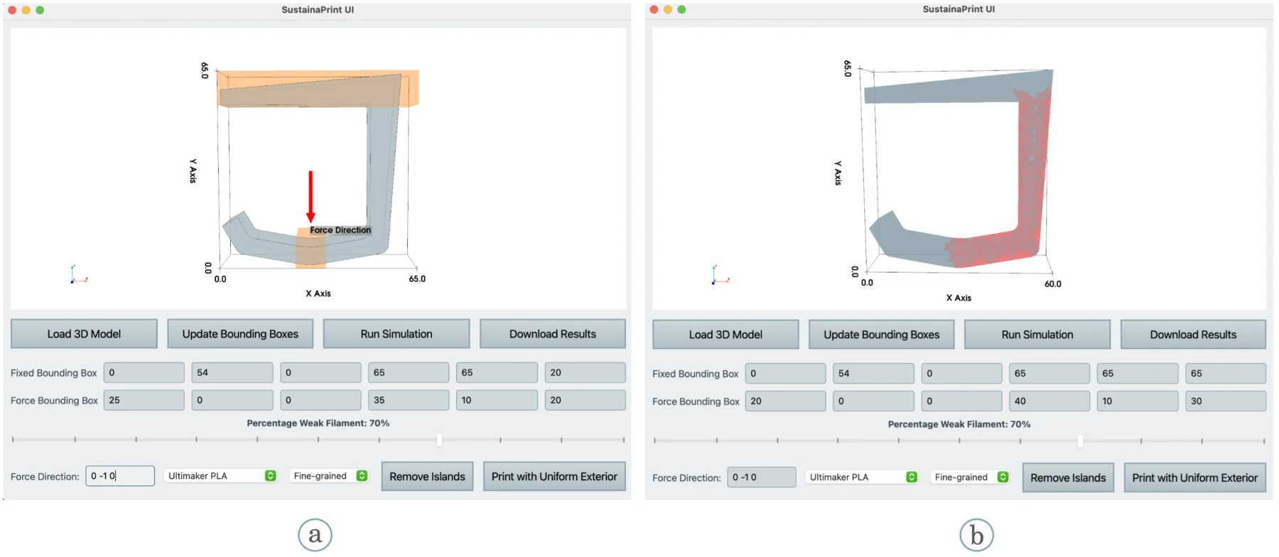
The paper's interface is a desktop app built with Qt and PyVista (ui.py in the release). The app at the top of this page is a browser version with the same layout: its Run Simulation button calls simulate() and its slider calls segment(), the same code as in the boxes.
Applications
SustainaPrint targets everyday objects that carry load. Click a card with a model to simulate it in the walkthrough.

Standing plant pot
Legged objects fail at the base under soil and water. The base and leg junctions are reinforced; the low-stress walls stay eco-friendly.
Bottle opener
Fix one end and push the other to mimic prying. Strong material goes where bending stress peaks.
Evaluation
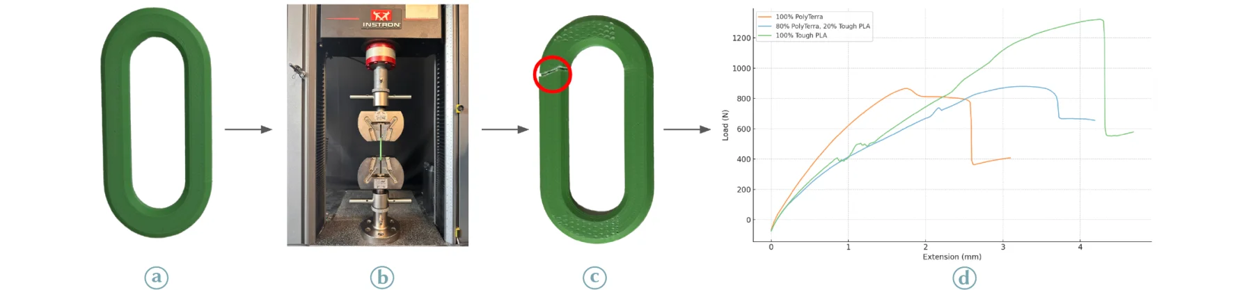
Five functional objects and five primitive geometries were printed in three conditions: 100% eco-friendly (Polymaker PolyTerra PLA), the SustainaPrint mix (80% PolyTerra with 20% virgin), and 100% virgin. Each was tested to failure on an Instron 3369 under the load that matches its use. The virgin filament was Ultimaker Tough PLA as a conservative high-performance baseline. The primitives were repeated with standard Ultimaker PLA.
Print parameters
| Printer | Ultimaker S5 | Infill density | 100% |
|---|---|---|---|
| Materials | PolyTerra, Ultimaker PLA | Infill pattern | Zig Zag |
| Diameter | 2.85 mm | Shell thickness | 0.8 mm |
| Resolution | 0.15 mm | Support | Tree |
Functional objects
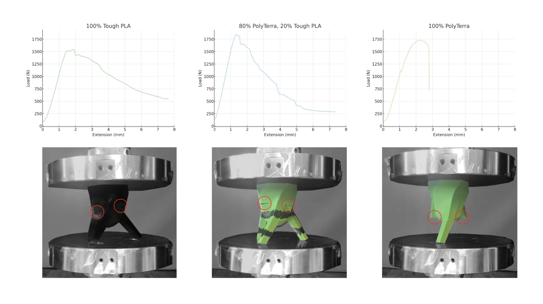
Five objects from Thingiverse: a table hook, a wall hook, a tripod plant pot, a headphone stand and a phone stand. The hooks were clamped and pulled apart; the others were compressed. SustainaPrint improved maximum force by 22.2% on average and by up to 78.5% on the table hook.
- Elongation at yield: 4.0 mm on average for SustainaPrint, vs. 3.7 mm eco-only and 4.4 mm virgin. In three of five models it tracked or exceeded virgin Tough PLA.
- Stiffness: from +20.5% (headphone stand) to −10.8% (plant pot), −2.0% on average relative to PolyTerra, reflecting material and geometry interactions.
- Toughness: +18.5% on average, peaking at +76.1% for the headphone stand.
Primitive geometries
Five primitives cover different load cases: a hook (tension and bending), a chain (pure tension), a beam (3-point bending, ASTM D790), a cylinder (axial compression, ASTM D695) and a dome (buckling under apex compression). With Tough PLA, SustainaPrint beat eco-only on all five, by 22.0% on average. With standard PLA the average gain was 44.1%. On the dome, SustainaPrint also outperformed 100% Tough PLA, which likely failed early because its stiffness made it brittle under buckling.

Trade-offs and alternatives
| Metric | No purge tower | With purge tower |
|---|---|---|
| Total waste | 0% | +37% |
| Print time | +11% | +45% |
| Virgin material saved | 80% | 80% |
Dual-head printers also draw more power: about 170–200 W measured on the Ultimaker S5, vs. reported 125 W for an Ender 3 and 100 W for a Prusa i3 MK3S.
Denser infill and SustainaPrint are complementary. On the ASTM D790 beam, SustainaPrint alone gains more than doubling infill from 15% to 30%, and combining both gains more still.
Limitations and future work
- SustainaPrint assumes a dual-extrusion printer and user-specified forces. Manual filament swaps for single extruders and automatic inference of use conditions are future work, as is tighter slicer integration.
- It does not address end of life. Up to 32% of hobbyist prints are discarded without reuse; SustainaPrint targets the upstream problem of virgin plastic during fabrication.
- Mixed-material parts are harder to recycle. Dissolution-based separation could help in future versions.
- Dual-material printing costs time and energy. Without a purge tower it adds no waste and saves up to 80% virgin plastic.
The tests cover static load failure; long-term fatigue is future work. The same approach could extend to experimental materials such as coffee-ground or clay composites.
BibTeX
@inproceedings{Perroni-Scharf:2025:SP,
  author    = {Maxine Perroni-Scharf and Jennifer Xiao and Cole Paulin and Zhi Ray Wang
               and Ticha Sethapakdi and Muhammad Abdullah and Patrick Baudisch and Stefanie Mueller},
  title     = {SustainaPrint: Making the Most of Eco-Friendly Filaments},
  booktitle = {The 38th Annual ACM Symposium on User Interface Software and Technology (UIST '25)},
  year      = {2025},
  address   = {Busan, Republic of Korea},
  publisher = {ACM},
  doi       = {10.1145/3746059.3747640},
  url       = {https://doi.org/10.1145/3746059.3747640}
}
Acknowledgements
We thank Faraz Faruqi and Leonardo Hernández Cano for their feedback and support, and gratefully acknowledge the HPI-MIT Designing for Sustainability Program, the MIT MAD (Morningside Academy for Design) Fellowship, and the MIT MathWorks Fellowship.